Reverse Power Relay Circuit Diagram
T2000 reverse power relay, din-rail mounted, selco usa Using motor circuit relays schematic reversible controlled circuitlab created electrical Relay reverse power protection flow mikro
Electrical Standards: Overload relay working principle and features of
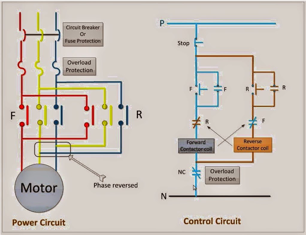
Reverse power relay Inverter indicator solar Power & control circuit for forward and reverse motor
Door locks
Reverse power relay t2000 selco diagramReverse power relay in power system Relays power circuit window using adding motor dc reversible boardReverse power relay basics and operation.
Circuit for reversible motor controlled using relaysWiring two spdt relays to operate a 12v dc motor forwards and back Wire polarity reverse relay diagram door switch electrical relays wiring diagrams trigger negative actuators locks positive circuit electronic double carRelay listrik kerja utility parallel connection dampak adalah.

Figure 3-113. reverse power relay test circuit
Power reverse relay circuit test tm figure 35c2 force army airReverse relay rr20 wisco ทดสอบ และ ดต Motor wiring dc 12v spdt relays two reverse diagram polarity diode operate forwards back kept blowing switchAdding relays to my power window circuit.
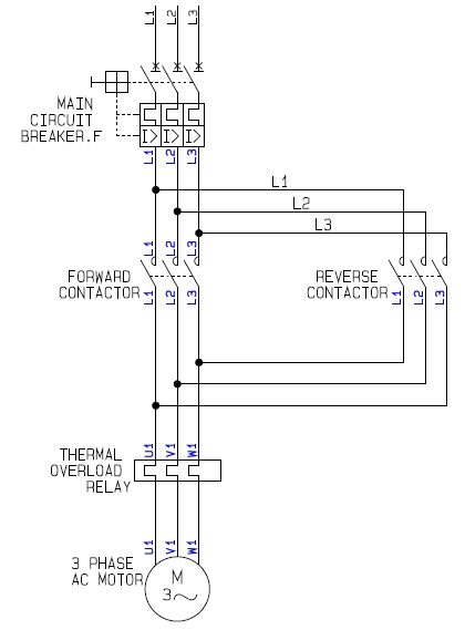
Relay reverse powerPower circuit forward control reverse motor electrical circuits engineering diagram stop wiring motors electric non mechanics info panel world board A how to guide for the power circuit of a forward reverse electricElectrical standards: overload relay working principle and features of.
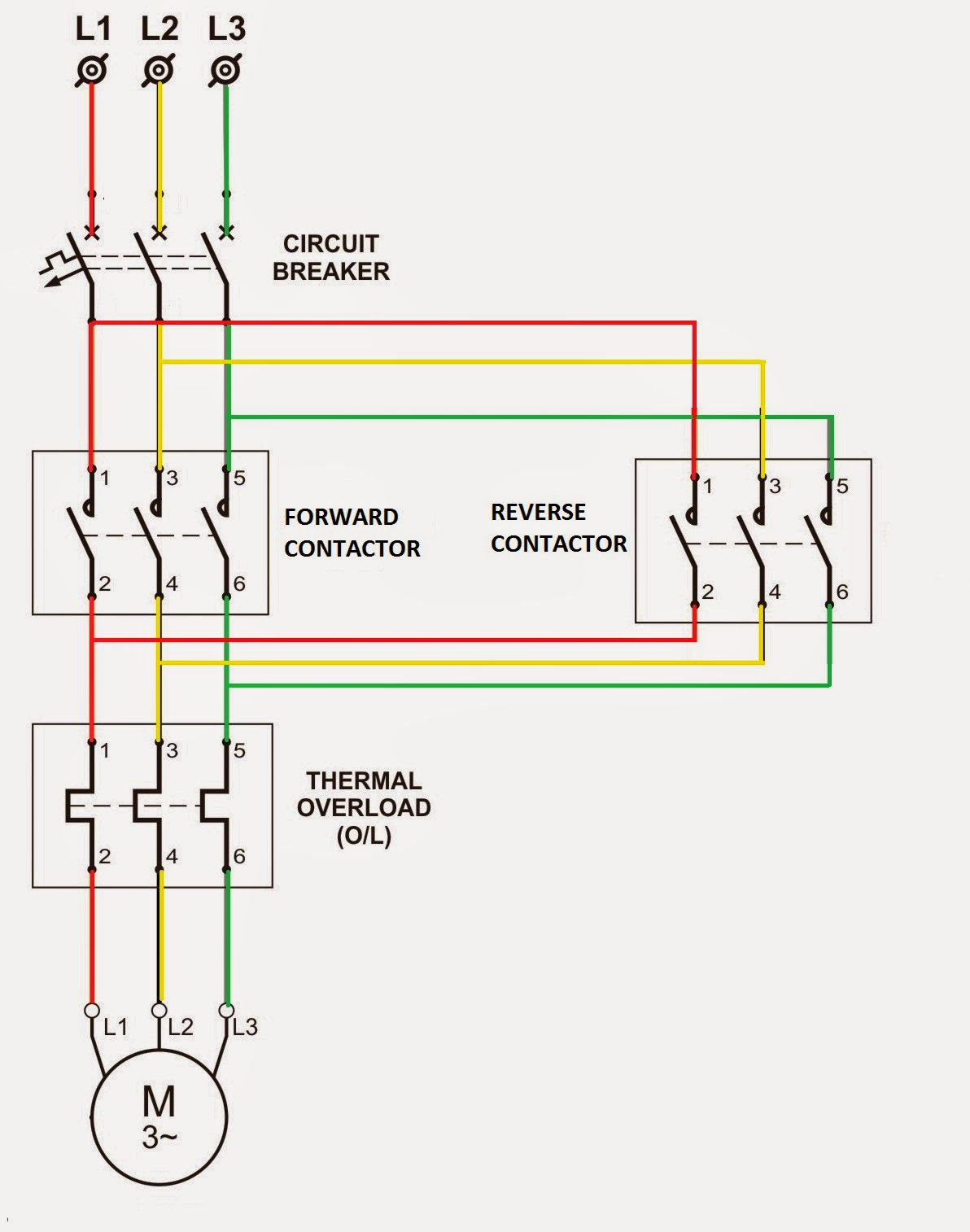
Relay diagram wiring contactor reverse phase overload circuit stop forward start ac motor power starter wire control direct dol magnetic
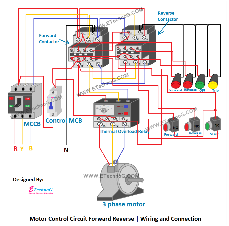
Rr20: reverse power relayWhat is reverse power relay? ~ electrical knowledge Motor control circuit forward reverseMotor control reverse forward circuit power electrical electric dol controller drawing schematic basic direct diagram line guide cad roller rotation.
.


Electrical Standards: Overload relay working principle and features of

wiring two SPDT relays to operate a 12v DC motor Forwards and Back

RR20: Reverse Power Relay | WISCO INDUSTRIAL INSTRUMENTS

Reverse Power Relay in Power System | Download Scientific Diagram

T2000 Reverse Power Relay, Din-Rail Mounted, SELCO USA

Power & Control Circuit for Forward and Reverse Motor | Non-Stop

A how to guide for the Power Circuit of a Forward Reverse Electric

Motor Control Circuit Forward Reverse | Wiring and Connection - ETechnoG

Circuit for reversible motor controlled using relays - Electrical